
my head is an animal colored vinylmy cat keeps bringing in baby bunnies
You must connect 5-12VDC power to the shield through the POWER terminal blocks or through the DC barrel jack on the Arduino and VIN jumper. Please sign in to subscribe to this guide. That comes in kit form, and is designed for breadboard use.  Motors need a lot of energy, especially cheap motors since they're less efficient. First make sure you are running thelatest version of Adafruit CircuitPythonfor your board. The NEMA 17 motor we have in the shop has a phase resistance of about 35 ohms, so it is a good match for the shield. source or the motor leads will act like antennae and broadcast it to the
  My shield doesn't work with my LED backpack. If you have a bipolar motor, do not Please sign in to subscribe to this guide. Tack one pin of each header, to get them set in place before more soldering.
  It tells us nothing about the electrical characteristics.
  supplies - one for the electronics and one for the motor. If the Green LED next to the power terminal block isn't lit up brightly do not continue! Doing this http://learn.adafruit.com/adafruit-16-channel-pwm-slash-servo-shield, http://learn.adafruit.com/adafruit-motor-shield-v2-for-arduino/install-software, Bluetooth Controlled Motorized Camera Slider. Arduino. Jason on reverse engineering the stepper wire pinouts. The library works identically for bi-polar and uni-polar motors. What Arduinos is this shield compatible with? The parameter can have one of 3 values: Note that the "FORWARD" and "BACKWARD" directions are arbitrary. Every shield you stack on will add, Check out our lovely servo shield, also stackable with this motor shield and adds 16 free-running servos per shield. One of the cool things about this shield design is that it is possible to stack shields. Note:For small DC motors like sold in the shop you might run into problems with electrical noise they generate and erratic behavior on your board. For a detailed explanation, see this guide. Running a stepper is a little more intricate than running a DC motor but its still very easy. We had to change the interface a little to support shield stacking, & we think its worth it! updated on Jul 09, 2013. These pins are not available for use on other processors. The default address is 0x60. Stackable, high current DC and Stepper motor shield, Yes, by stacking shields! Why don't you just design capacitors into the shield? The Shield will not function without an external power source! I'd recommend a 5v/2A supply: That product seems to be out of stock. When I am testing all 4 stepper motors together, they stop after 9-10 cycles. They have a 3-pin 0.1" female header connection with +5V, ground and signal inputs. Sorry. It does not work for 3V Each shield you want to stack on top of must have stacking headers installed. Check our instructions for how to do so. Some backpacks have a default address of 0x70. My Arduino freaks out when the motors are running! Why don't you just design capacitors into the shield? The shield is addressable from0x60-0x7F. 0x70 is an"all call" address that all boards will answer to. You will need 3 total. If you're using M1 its 1, M2 use 2, M3 use 3 and M4 use 4. motors unless you overdrive them at 5V and then they will burn out Now you can install the terminal blocks and jumper Next we will install the terminal blocks. Once you've tacked and straightened all the headers, go back and solder the remaining pins for each header. Adafruit_StepperMotor *myStepper2 = AFMStop.getStepper(200, 1); Adafruit_StepperMotor *myStepper3 = AFMStop.getStepper(200, 2); // On the bottom shield connect a stepper to port M3/M4 with 200 steps. A 7.5 degree/step motor has 360/7.5 = 48 steps. See this motor guide FAQ page for information on capacitors you can solder to the motor to reduce noise. The binary address that you program with the address jumpers is added to the base I2C address.To program the address offset, use a drop of solder to bridge the corresponding address jumper for each binary '1' in the address. source or the motor leads will act like antennae and broadcast it to the For security reasons, an e-mail has been sent to you acknowledging your subscription. It is tested to work with Duemilanove, Diecimila, Uno (all revisions), Leonardo and Mega/ADK R3 and higher. Please remember that this subscription will not result in you receiving any e-mail from us about anything other than the restocking of this item. Adafruit_StepperMotor *myStepper2 = AFMStop.getStepper(200, 1); Adafruit_StepperMotor *myStepper3 = AFMStop.getStepper(200, 2); // On the bottom shield connect a stepper to port M3/M4 with 200 steps. HELP! #steps is how many steps you'd like it to take. RPM depends on the motor and the voltage which is unknown. What on earth could you do with that many steppers? This is a very very very bad idea unless you are sure you know what you're doing! The file can be found in hardware/libraries/wire/utility/twi.h.Find the line with: "#define TWI_FREQ 100000L"and change it to "#define TWI_FREQ 400000L" Or, you can add the following code to your setup() function: (Note: this line must be inserted after the call to begin()). This page (FAQ) was last updated on Jul 29, 2022. For unipolar motors: to connect up the stepper, first figure out which pins connected to which coil, and which pins are the center taps. We have upgraded the shield kit to make the bestest, easiest way to drive DC and Stepper motors. If you re-address your backpack, it will work with the shield. GND and either 5v (default) or 3.3v are required to power the logic on-board. If, for any reason, you would like to unsubscribe from the Notification List for this product you will find details of how to do so in the e-mail that has just been sent to you! Then flip the board over so its resting on the four headers. My motor doesnt work!But the servos work FINE! This will be safe to use with supply voltages up to 12v. These motors generate a lot of brush noise and usually need the full 3-capacitor treatment for adequate suppression. Most people will probably just stack two or maybe three but hey, you never know.
 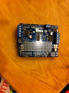 But my motor already has a capacitor on it and it still doesn't work. a great page on how to install the library bundle, See this motor guide FAQ page for information on capacitors you can solder to the motor to reduce noise. The file can be found in hardware/libraries/wire/utility/twi.h.Find the line with: "#define TWI_FREQ 100000L"and change it to "#define TWI_FREQ 400000L" Or, you can add the following code to your setup() function: (Note: this line must be inserted after the call to begin()). The top shield does not have to have stacking headers unless you eventually want to put something on top of it.The only thing to watch for when stacking shields is every shield must have a unique I2C address. Stepper# is which port it is connected to. On the Arduino UNO these are also known as A4 and A5.
 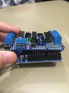 If you need to control a lot of servos, you can use our 16-channel servo shield and stack it with this shield to add a crazy large # of servos.Stacking shields is very easy. You must connect 5-12VDC power to the shield through the POWER terminal blocks or through the DC barrel jack on the Arduino and VIN jumper. NEMA-17 is just a motor frame-size designation. Each shield you want to stack on top of must have stacking headers installed.
  Hobby servos are the easiest way to get going with motor control. Nextconnect to the board's serial REPL so you are at the CircuitPython>>>prompt.
  On the Mega these are also known as Digital 20 and 21. That means they can be driven forwards and backwards. I have good solid power supplies, but the DC motors seem to 'cut out' or 'skip'. GND and either 5v (default) or 3.3v are required to power the logic on-board. There are two places you can get your motor 'high voltage supply' from. The center taps should both be connected together to the GND terminal on the motor shield output block. "Interleave" means that it alternates between single and double to get twice the resolution (but of course its half the speed).
 See this guide for details:Matching the Driver to the Stepper. Please read the user manual for information about appropriate power supplies. Make sure the jumper is removed from the motor shield. You can use any DC motor that can be powered by 6V-12VDCFirst, restart the IDE to make sure the new library is loaded. My motor doesnt work!But the servos work FINE! The most basic function (and the default) is to do one single coil step. As of Arduino 1.5.6-r2 BETA, there is a bug in the Due Wire library that prevents multiple Motor Shields from working properly! If you want something beefier, cut the trace going to the optional servo power terminal and wire up your own 5-6V supply! That's it! You can power the Arduino via the DC Barrel jack.
  Works with Due with 3.3v logic jumper. Some small hobby motors are only intended to run at 1.5V, but its just as common to have 6-12V motors. The terminal block has a protection FET so you will not damage the arduino/shield if you wire up your battery supply backwards, but it wont work either!Here's how it works: Say a wall adapter or a single battery pack with 6-12VDC output, simply plug it into the DC jack on the Arduino or the 2-pin power terminal block on the shield. This library is not compatible with the older AF_Motor library used for v1 shields. What pins are/are not used on the motor shield? (on the motor itself!) will prevent brownouts. You can also call the onestep function with two optional keyword arguments. You can't run motors off of a 9V battery so don't waste your time/batteries! Tested compatible with Arduino UNO, Leonardo, ADK/Mega R3, Diecimila & Duemilanove. The Stepper and DC motor connections will not work if the onboard green Power LED is not lit brightly! The actual speed of the motor will depend on several factors, including: The motor, the power supply and the load. That is a 1A (1000mA) supply. If you are using a unipolar motor with 6 wires, you can connect the two 'center coil wires' together to GND. Adafruit Motor/Stepper/Servo Shield for Arduino v2 Kit, Stepper motor - NEMA-17 size - 200 steps/rev, 12V 350mA, Small Reduction Stepper Motor - 5VDC 32-Step 1/16 Gearing, Small Reduction Stepper Motor - 12VDC 32-Step 1/16 Gearing, "You don't make progress by standing on the sidelines, whimpering and complaining. For a detailed explanation, see this guide. These pins are not available for use on other processors. Adafruit_MotorShield AFMSbot(0x61); // Rightmost jumper closed, Adafruit_MotorShield AFMStop(0x60); // Default address, no jumpers, // On the top shield, connect two steppers, each with 200 steps. Works with Mega/ADK R2 and earlier with 2 wire jumpers. The speed parameter is a value between 0 and 255.Note that setSpeed just controls the power delivered to the motor. This shield will make quick work of your next robotics project! The I2C base address for each board is 0x60. Many small DC motor have a lot of "brush noise".
  It tells us that the motor body is 1.7" square. I get the following error trying to run the example code: "error: Adafruit_MotorShield.h: No such file or directory.", Make sure you have installed the Adafruit_MotorShield library. For security reasons, an e-mail has been sent to you acknowledging your subscription. To begin controlling motors, you will need to install the Adafruit_Motor_Shield_V2_Library library (code on our github repository). If you see erratic behavior like the motor not spinning or the board resetting at high motor speeds this is likely the problem. We kept the ability to drive up to 4 DC motors or 2 stepper motors, but added many improvements:Instead of a L293D darlington driver, we now have the TB6612 MOSFET drivers with1.2A per channel current capability (you can draw up to 3A peak for approx 20ms at a time). This feeds back into the Arduino circuitry and causes unstable operation. Servos are powered off of the same regulated 5V that the Arduino uses. If you need to control a lot of servos, you can use our 16-channel servo shield and stack it with this shield to add a crazy large # of servos. You can use 2 DC hobby servos that run on 5V and up to 4 DC motors or 2 stepper motors (or 1 stepper and up to 2 DC motors). All pins are broken out into 0.1" spaced header along the edges of the shield. Request the DCmotor from the Adafruit_MotorShield: with getMotor(port#). All boards will respond to address 0x70 - regardless of the address jumper settings. connect to the middle pin (GND). The right-most jumper is address bit #0, then to the left of that is address bit #1, etc up to address bit #4. That should be fine.
  There are two ways to do this, If the Green LED isn't lit up brightly do not continue - you must power it via the VIN jumper or the terminal block. This means the speed is very smooth and won't vary!Note that the H-bridge chip is not meant for driving continuous loads of 1.2A, so this is for small motors. If you're lucky your motor came with some sort of specifications. The motor shield simply brings out the PWM output lines from Arduino pins 9 and 10 to two 3-pin headers so that its easy to plug in and go. If you're using M1 and M2, its port 1. You cannot use a 9V battery for this, it must be 4 to 8 AA batteries or a single/double lead acid battery pack. updated on Jul 09, 2013. There is no active current limiting, so you need to choose a stepper motor that will not try to pull more than that. The noise must be suppressed at the Break apart the 0.1" header into 6, 8 and/or 10-pin long pieces and slip the long ends into the headers of your Arduino, Place the assembled shield on top of the header-ed Arduino so that all of the short parts of the header are sticking through the outer set of pads, Solder each one of the pins into the shield to make a secure connection. You have been successfully subscribed to the Notification List for this product and will therefore receive an e-mail from us when it is back in stock! For bipolar motors: its just like unipolar motors except theres no 5th wire to connect to ground. It is close, but at 1040mA, a 1A supply will probably overheat. The image of the power supply is below. The first parameter specifies how many steps to move. The default address is 0x60. When using external servo power, be careful not to let it short out against the USB socket shell on the processor board. This also makes it drop-in compatible with any Arduino, such as the Uno, Leonardo, Due and Mega R3.Completely stackable design: 5 address-select pins means up to 32 stackable shields: that's 64 steppers or 128 DC motors! Adafruit_MotorShield AFMSbot(0x61); // Rightmost jumper closed, Adafruit_MotorShield AFMStop(0x60); // Default address, no jumpers, // On the top shield, connect two steppers, each with 200 steps. The NEMA 17 motor we have in the shop has a phase resistance of about 35 ohms, so it is a good match for the shield. Check our instructions for how to do so. Even small DC motors can draw up to 3 Amps when they stall. I have no idea but if you come up with something send us a photo because that would be a pretty glorious project.Lots of other little improvements such as a polarity protection FET on the power pins and a big prototyping area. You have been successfully subscribed to the Notification List for this product and will therefore receive an e-mail from us when it is back in stock! Stackable, high current DC and Stepper motor shield, Yes, by stacking shields! Theres tons of information about the pros and cons of these different stepping methods in the resources page.You can use whichever stepping method you want, changing it "on the fly" to as you may want minimum power, more torque, or more precision.By default, the motor will 'hold' the position after its done stepping. The I2C base address for each board is 0x60. Doing this You make progress by implementing ideas". They're much easier to use than soldering direct, just use a small screwdriver to release/attach wires! This is OK for the small hobby servos suggested. this will reduce noise that could be feeding back Insulate the top of the USB socket with some electrical tape. into the circuit (thanks. My Arduino freaks out when the motors are running! Flip the board over so that you can see & solder the pins of the terminal blocks, Solder in the two pins of the external power terminal-block. Next up, servo connections. This is done with the address jumpers on the lower edge of the board. Then every time you want the motor to move, call the step(#steps, direction, steptype) procedure. Details of the setup and problem below. Arduino. Note that you may have problems with Arduino resets if the battery supply is not able to provide constant power, so it is not a suggested way of powering your motor project. On the Leonardo these are also known as digital 2 and 3. With DC motors you can build fun moving projects like robots or remote controlled cars that glide around with ease. rest of the system! The Arduino USB is connected to the computer. A simple rule of thumb is to use a motor with a phase resistance of 10 ohms or more. Adafruit_StepperMotor *myStepper1 = AFMSbot.getStepper(200, 2); Adafruit_DCMotor *myMotor1 = AFMSbot.getMotor(1); AFMSbot.begin(); // Start the bottom shield. I am using the Arduino Uno power supply (supplied along with the Arduino starter kit) to power this. However, if you have code for the older shield, adapting the code to use the new shield isn't difficult. All boards will respond to address 0x70 - regardless of the address jumper settings. This is the "all call" address of the controller chip on the motor shield. There are several AccelStepper examples included with the motor shield library. The run() function controls the motor state. You will need to purchase Arduino stacking headers for this step, the shield does not come with them. This is the "all call" address of the controller chip on the motor shield.
  faster, Try soldering a ceramic or disc 0.1uF capacitor between the motor tabs The plastic tab is only there to make it easier to grab. Then you have access to the following options: The function returns the current step 'position' in microsteps which can be handy to understand how far the stepper has moved, or you can ignore the result.